At one of the early meets, Doug kindly gave me some old organ amps for me to play with and while I have looked at them from time to time, I've never got around to doing anything with them. However, now is the time.
In particular, I have started to look at two of the beasts which are fairly similar. They both appear to be the Baldwin 40 watt models with a quad of 6L6 tubes. One is driven by an octal 6SL7 and the other by nine pin 12AX7's. First I am investigating the 6SL7 version. Here are some photos. You may click on the photos to see larger versions.
Some Baldwin history is available here.
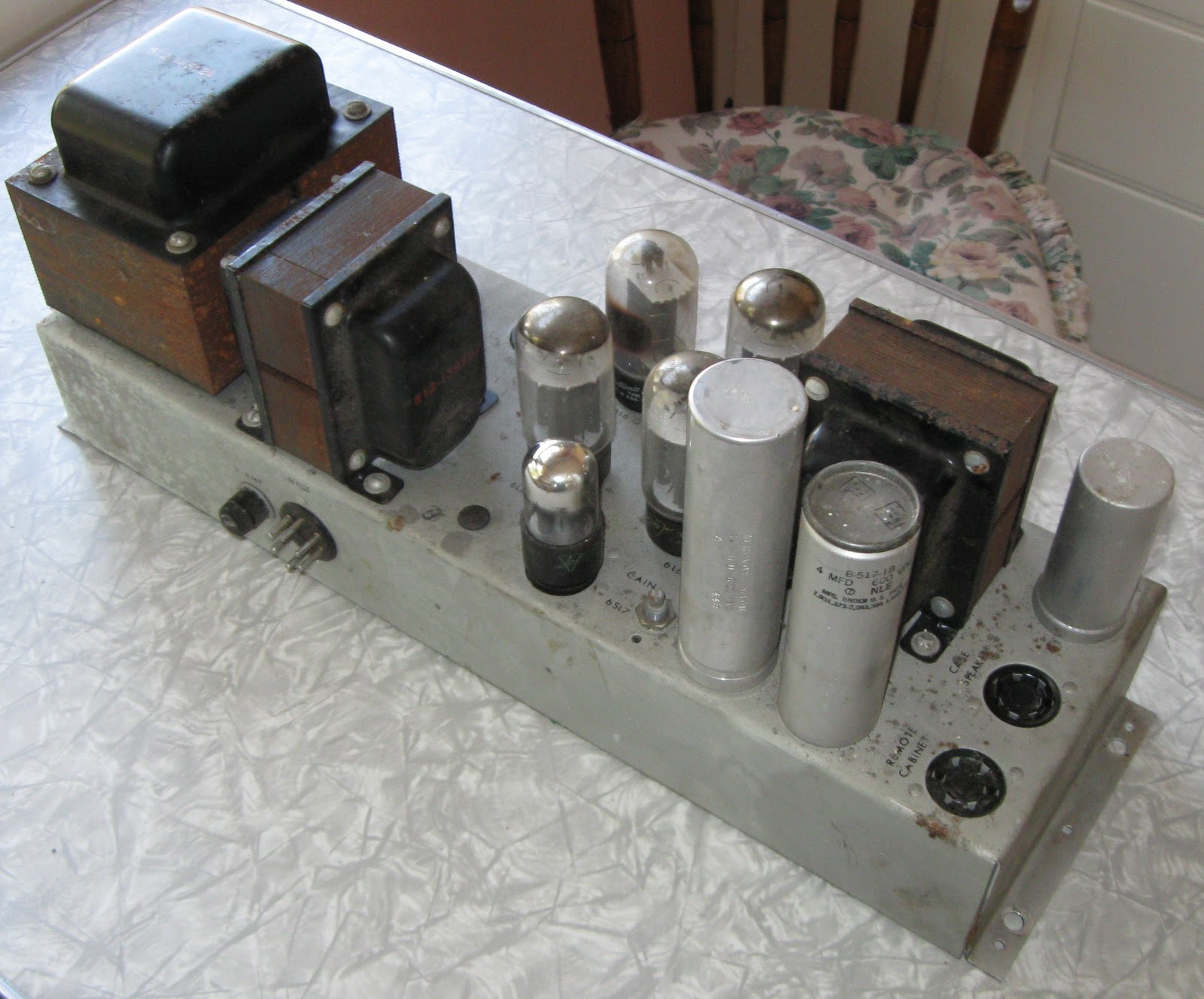
The four larger tubes are 6L6 and the smaller one in front is a 6SL7.


The two empty octal sockets at the top left use 5U4-G rectifier tubes.
To the left is the power transformer, followed by the choke and the output transformer on the right. All have rust on them.

The 6 prong plug has the input.

Presumably the chassis number.

Each transformer comes with a number. This is actually a choke / inductor.

The massive power transformer with its number. The output transformer has the number 512-14633D. It is possible they were made by CinTran (see reference here)
Here are some photos of the guts.

The power transformer is on the right with the two 5U4 sockets just to the left.

The other end.

The area around the 6SL7 is quite congested. The four copper coils connect to the 6L6 plates and you find discussion about them here.

To the left is the hole for the leads to the choke.

I did find a schematic which looks pretty close to what is actually in this amplifier. My amp does not have the 6SQ7 input stage. Unfortunately I have not been able to find the schematic again on the web so if you know where it is, let me know.

As an aid to exploring the wiring, I have made a Visio version that I still haven't finished, but I will get there eventually.

There are some questions I have that have puzzled me.
- When I first looked at the schematic, I noticed that the choke (2) was connected to the center tap of the power transformer and a 4uf capacitor. The other end is connected to ground instead of another capacitor. I thought this was probably a mistake in drawing the schematic, but it does connect to ground at a lug on a 6L6 socket.The choke has a DCR of 87 ohms. Any ideas?
- Why did the designers place the capacitors at the far end of the amp from the rectifiers? The wires connecting the choke to ground and the 4 uf capacitor are twisted, but they do run right next to the input signal.
- In the spirit of preservation, I'm not thinking of making any changes to the circuit or even the components except for possibly the electrolytic caps. The coupling caps seem to be ok and the carbon comp resistors appear to be reasonable close to value. Are there any other changes that I might contemplate?
- My variac died recently. Any ideas for bring the beast back to life in a gradual fashion?
- How to restore the finish for the steel casework? I did come across one interesting idea here which I will try in an inconspicuous area for the steel work. I tried polishing one up with polishing compound but it left uneven spots in it. The only true polish I had laying around was a bottle of Maguires PlastX clear plastic cleaner and polish. I use it on dust covers on my turntables. It takes the oxidation off of them and hides swirls and scratches. I tried it and it immediately turned my paper towels black with the oxidation. I wiped down a good size spot and cleaned it off and the metal really stood out. I used Old English lemon oil to recoat the metal and help remove the film left by the Maguires.
- Ideas for the rust on the transformers would be welcome.
This comment has been removed by a blog administrator.
ReplyDeleteThis comment has been removed by a blog administrator.
DeleteHi Ron,
ReplyDeleteHow is it with your Baldwin amp project? Have you completed it ? I recently acquired a unit similar to yours and I'm interested to find out how I can get it up to work. I look forward to hearing from you soon.
Thanks
David
Hi David,
ReplyDeleteUnfortunately I got distracted by other projects so I have not made any progress. At least you have prodded me to get going again. I will be away from home until September, so perhaps we could do this a dual project to help each other out. I always welcome other people's ideas.
ray
Hi Ron,
DeleteSure, no problem. I'll try to figure out how I could proceed. I tried to scout the internet for a circuit drawing for this amp but couldn't find any. I heard some people were successful in converting them into home hifi but no one seems to publish any schematic.
David
For the (mono) 40w 4/6L6 version one expert wrote..
ReplyDeleteLeave the amp as is. Recap it using double the values for the filter caps. Add a 100uf 100v cathode bypass cap. Add an RCA jack right off the volume pot. Add binding posts and make sure that your negative feedback resistor (3.9k or 39k depending on which year yours is) goes to the 16 ohm tap (green if I recall.) Install a bucking transformer to knock off 6.3 or 12v in it as these were designed to run on 110v and they WILL cause the tubes to red-plate as they sit. You will be surprised by the sound of the stock circuit, they are Mac killers. (Now I am not use if he was referring to the 12ax7 or 6SL7 driver version)
Hope this is of some help.
The Baldie (organ) tube amps are perhaps the best kept secret in tube amp world. Picked up for less than a few hundred dollars in perfect condition. These have been tweaked for home hi-fi use and said to be mac killers, and built into guitar amps altho no YT vids to date on the big Baldies guitar amps but some have, and I have a few intended for just that purpose!
ReplyDeleteCould you imagine the wonderful tube tone from a PPP 4/6L6 40w baldie/JTM45 or 59 Bassman? or Bogner XTC? Or just using it as a power-amp for a great guitar preamp? These amps have massive iron so reliability is never a issue, they are built better than the original Marshalls and Fenders!
Don't let these old Baldie tube amps go to the junk pile, repurpose them for home stereo use, or guitar amps, you won't be disappointed.
I just got my hands on one of these ,but i do not have the imput cable. can i make one?
ReplyDeleteI seen this post and thought I would mention that I have 2 of these amps. One is working and the other seems to have an issue. Yes, input cable can be made.
ReplyDeleteHi yall. So happy I found out what these mono blocks were!! Have 2 how and where could I have them looked at and fixed maybe in astoria queens area NY. can you help thanks
ReplyDelete